Hope this answer will be useful to you. To copy and paste the drawing into 3D space-.

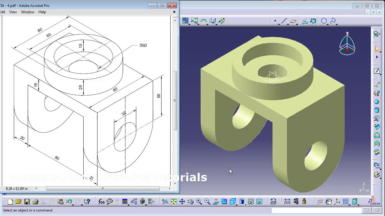
How To Create A Mechanical Part Using Catia Part Design Surface Design Mechanical Design Mechanical Engineering Design
Select all affected dimensions right click and select Line-Up option.

. Leveraging the capabilities of Microsoft Excel you can easily control design parameterssuch as dimensions suppression states and materialsthrough cells in a spreadsheet. Smaller dimensions should be placed inside larger dimensions. Double-click on the 3736 dimension and the Constraint Definition box will open.
If not we need to enlarge or shrink the drawing into the correct size. After you click the second radius and while the dimension is still active hold down the ctrl key and youll see some little squares appear at the end of the extension lines of the dimension. The Line-up dialog box appears.
It didnt work because it outputs an error if any part of the domain is not able to be evaluated for example negative inputs to the squareroot using Mathematica to export an stl file and import to solidworks worked but not well because the resolution was not great as a mesh was exported. Select a planer support eg. Move the cursor over one end or the other and youll get the option to drag the dimension point to different locations.
When making a drawing in CATIA it is common to add an axis line to features. How to display the weight mass center of gravity and surface in CATIA V5. CATIA switches the current workbench to the sketcher.
On the icon is a dimension with a spy glass But beware you will loose the ability to see if the dimension is disconnected from 3D therefore I recommend you to turn it off only before drawing printing and then turn it on again. Datum plane planer solid face from the specification tree or by clicking the support directly. B Dimension Creation.
It thinks you are trying to show a revolved diameter. If we need to take this a step further within Tools Options Mechanical Design Drafting Dimension setting By default create dimensions on circles to Edge will take care of this in a more permanent fashion. Check if the displayed dimension is 50mm.
You can turn off the displaying of colors in the drawing if unselecting the icon on the bottom menu in drawing mode. Your dimensions may be different. Dimensions should be grouped together as much as possible.
Dimension values should not overlap themselves dimension extension or visible lines. Click on the scale line of the drawing. The next step is to edit the two dimensional constraints.
Generally an axis created anywhere in CATIA tells it to gear up for some type of rotation. Edit the 3736 dimension to 4 OK. And how to line-up dimensions on the drawing.
After you choose the material for you part you can very easy track your dimensions. Sub CATMain Dim MyDoc As DrawingDocument Dim MySelection As Selection Dim MySheet As DrawingSheet Dim MyDrawingView As DrawingView Dim MyDimensions As DrawingDimensions Dim MyDimension As DrawingDimension Dim MyText As DrawingText Dim oValues5 Set MyDoc CATIAActiveDocument Set MySheet. You can customize given options when creating or re-positioning dimensions.
Once you have your model fully constructed though there comes the question of. Hope you found todays CATIA Tip in a Minute or Less to be useful if not just interesting. CATIA V5R16 surface modeling Mouse Tutorial 2A To confirm that the size of the drawing is correct- Click Dimensions icon.
Dimension text should be horizontal preferred or aligned with parallel to dimension line. CATIA V5R16 Fundamentals Create a Sketch 1. The dimension will have a curve above the numerical display to.
Or go to the main menu Tools Positioning Line-up. To reduce the time or you can think of this as a work around you can create a sketch in the part file to represent the mating geometry then show the sketch dimensions in the drawing view without creating a feature for it. From your tree select the top element name of the part right click and choose Proprieties.
Which is why when you dimension to an axis in CATIA the system will give you a number that is double the value. Dimension following the mouse ctrl toggles. SOLIDWORKS design tables help you to efficiently create and manage model configurations.
Once you create and dimension the sketch in the part make sure it is shown. Select the Sketcher Icon from any workbench where is possible to create a sketcher eg. Then CATIA calls to Select a dimension or geometry as reference to line-upin the bottom left corner of the screen.
Using fusion360s equation driven surface command. October 29 2007 1051 PM in response to James Bishop Hello there In 2D drafting when a length dimension is created Right-click will give you an option of curvelinear. Pick the right side of the rectangle Place the 1952 inch dimension.
Surface modelling in CATIA is supported by generative shape design. You can decide that the dimension line is positioned according to the cursor following it dynamically during the creation process. It offers capability to model the complex surfaces in various engineering applications such as in automobiles aeroplanes etc.
Select the Dimension tab in OptionsDimension Creation. And to do that you have several methods to display that.

I Need Drawing For Practice In Wireframe And Surface Design Grabcad Questions

I Need Drawing For Practice In Wireframe And Surface Design Grabcad Questions
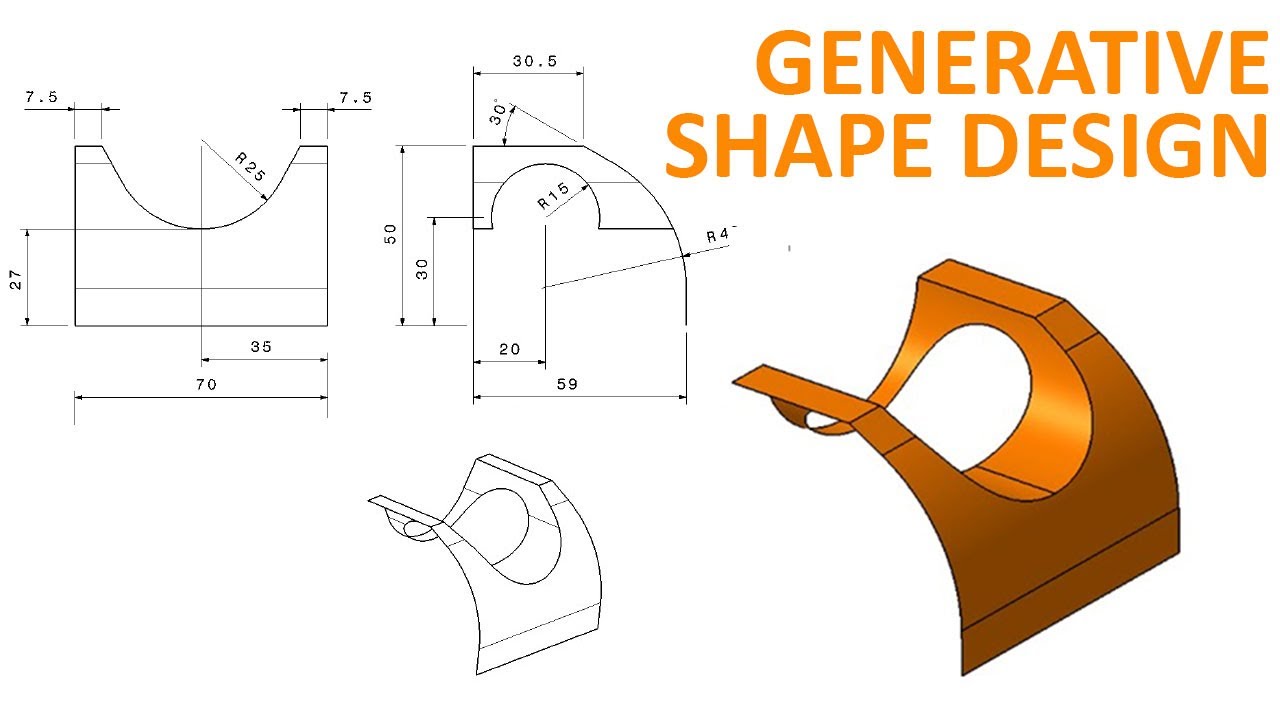
Generative Shape Design 1 Catia V5 Beginner Tutorial How To Use Extrude And Split Youtube
I Need Drawing For Practice In Wireframe And Surface Design Grabcad Questions
Catia Surface Design Exercises For Beginners 2 Catia Surface Design Tutorial Youtube

I Need Drawing For Practice In Wireframe And Surface Design Grabcad Questions

Pin On Catia V5 Video Tutorials

Catia Simple Surface Design For Beginners Youtube
0 comments
Post a Comment